
LAD-5
The LAD program took a significant turn in Spring 2022, as SEB began to explore the use of 3D-printing in the manufacturing of critical flight hardware components. Incorporating 3D-printing into our workflow has allowed the team to accelerate its timelines tremendously.
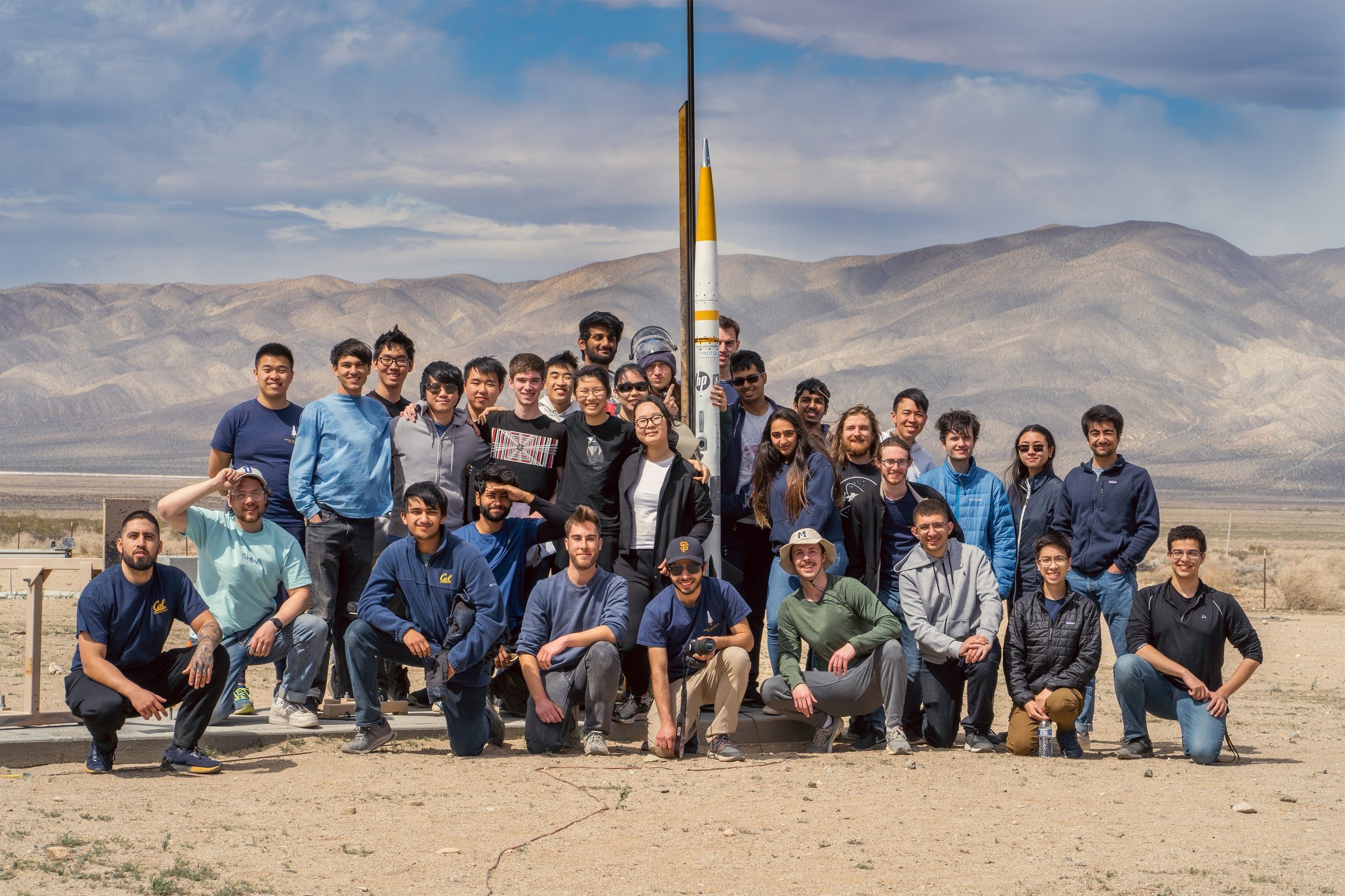
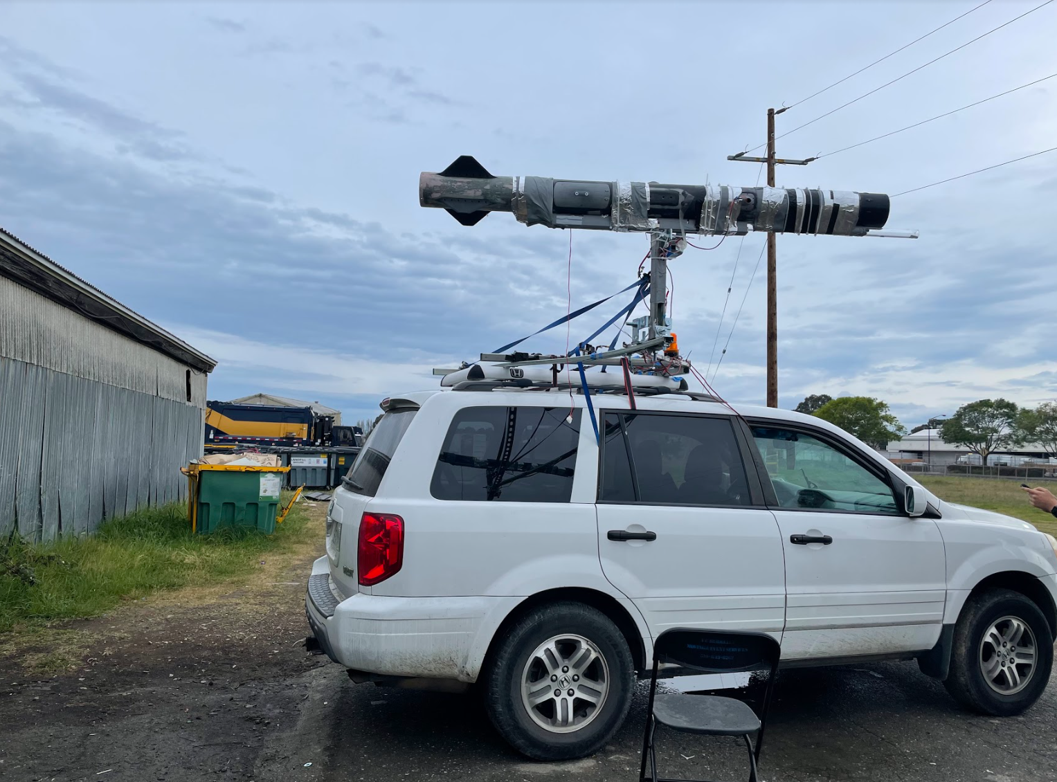
With the goal of evaluating the use of a 3D-printed inner airframe structure with a composite overwrap layer, SEB designed the LAD-5 vehicle over the winter break of December 2021. Standing at 2.2 meters in height and having an outer diameter of 120mm, LAD-5 was designed to fly to 11,000 feet above ground level in the transonic regime.
0.83 Mach
TOP Speed
4.8 Inch
Rocket Diameter
10,337 Feet
TOP Altitude
8.4 Feet
Rocket Height
PROJECT HIGHLIGHT
3D Printed Airframe
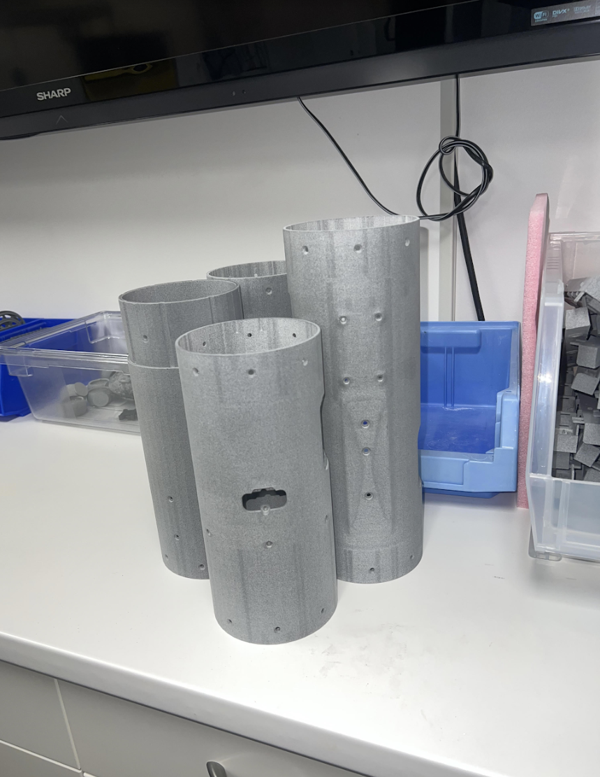
Printed substrate components
The airframe substrate was printed out of PA-12 using the Jet Fusion 5200 printer. As-printed, the airframe structure contained all of the requisite internal locating features, bulkheads, and hatches necessary for integration. The three-layer laminate was laid up directly onto the PA-12 surface and allowed to cure at ambient conditions. From a process perspective, the procedure directly replicated that of traditional airframe construction, with the exception that the “mandrel” (i.e. the PA-12 substrate) was now left in place after curing, serving as a non-structural component.
Producing the airframe of LAD-5 in this manner permitted a high degree of modularity and reconfigurability on a section-by-section basis. Integration was dramatically more efficient compared to a traditional, annular composite airframe through the use of threaded heat-set inserts which could be installed directly into the thermoplastic, allowing standard threaded fasteners to be used for coupling sections together and mounting auxiliary components, such as a standalone avionics bay.
Assembly
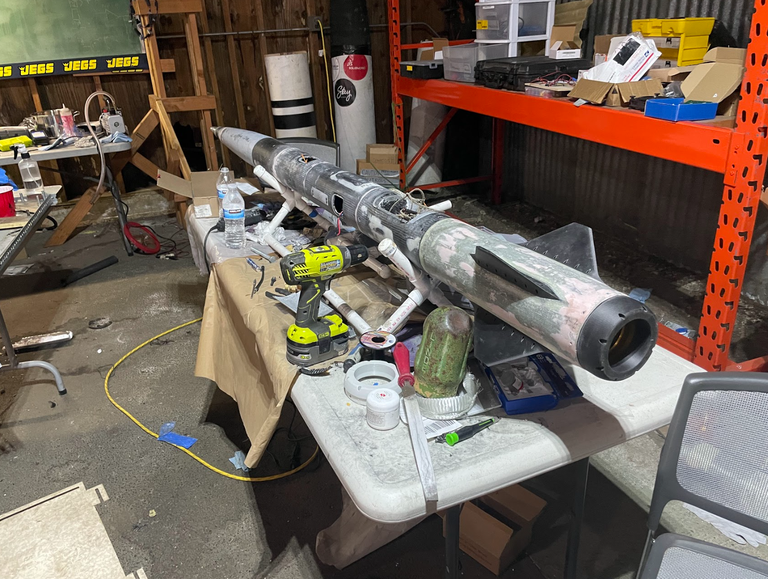
Final integration included a lot of miscellaneous cleanup operations, including filing hatches, sanding down fits, and smoothing down the composite skin with Bondo gap filler. Once it was all together, the vehicle weighed 14.2 kg dry.
Room for Improvement
Despite clear process advantages compared to full-scale traditional airframe manufacturing, especially in the integration stages, the production of a composite LAD airframe nevertheless suffered from several difficulties. In particular, through-holes needed to be drilled out after the composite skin cured; although the location of holes was determined by the printed part, the holes had to be drilled from the outside in, making it a non-trivial challenge to attain the positioning tolerance required for hole patterns. Furthermore, the composite layer had to be sanded and smoothed. Surface imperfections (nicks, pockmarks, and deep scratches) were addressed using the application of body-filling compound, which created additional sanding and polishing steps. On top of this higher than expected degree of manual labor, the uniformity issues of ambient-cure composites remained.
PROJECT HIGHLIGHT
3D Printed Airframe
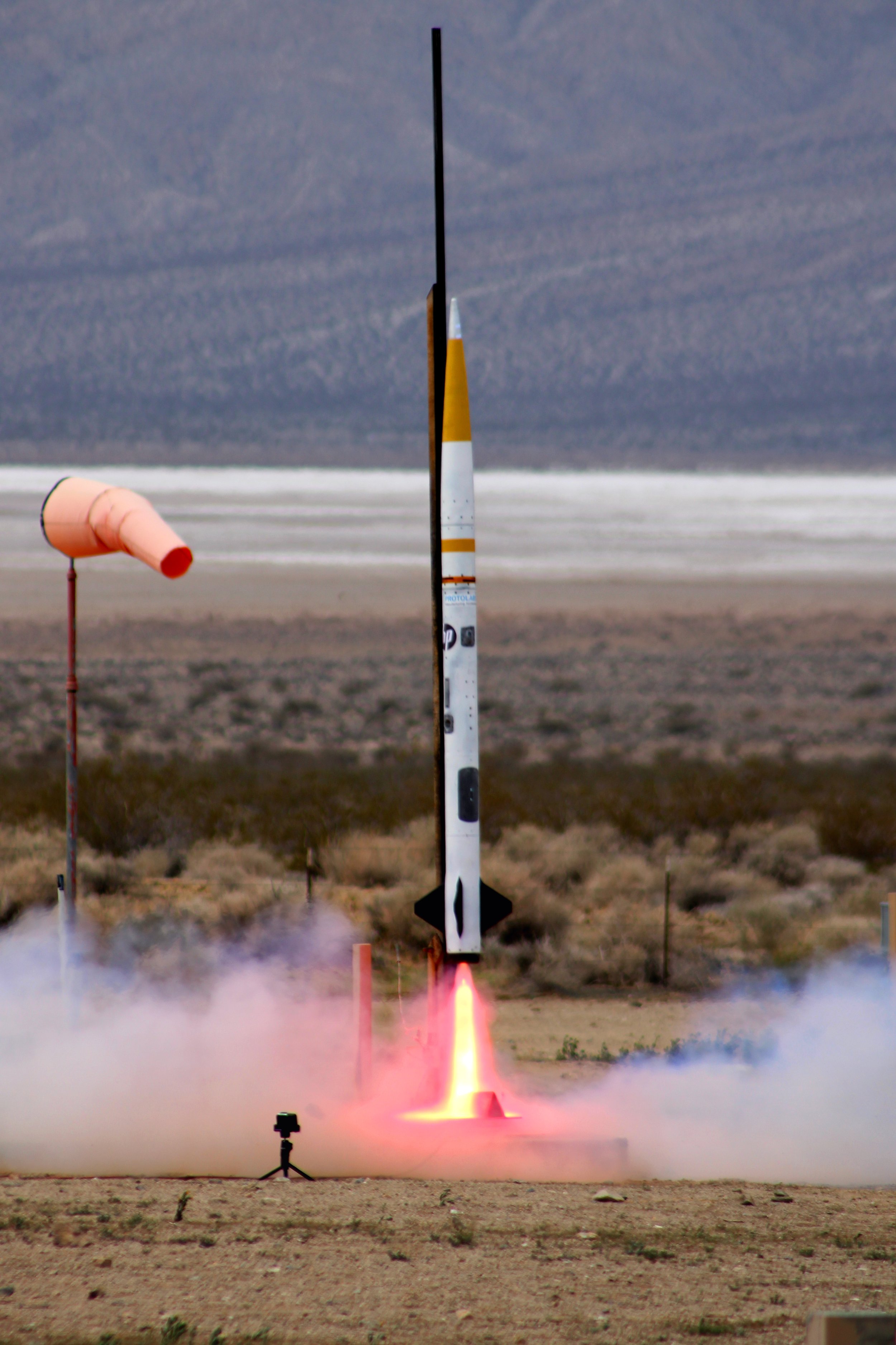
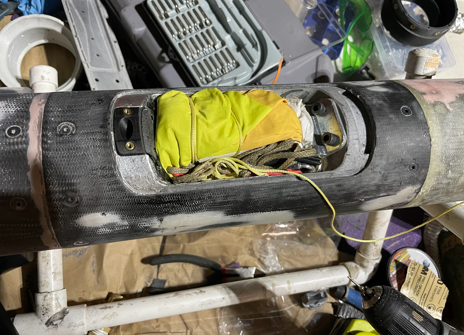
After most components were at an acceptable level of readiness, the main item that remained on the itinerary was recovery testing. SEB has repeatedly learned that recovery is quite often the most difficult part of constructing high powered rockets, and so a better method to validate the efficacy of these systems was sought for. In order to validate the unusual parachute deployment concept (drogue parachute side deploy), we needed to take the entire vehicle up to speed to simulate a midair deployment. C-channel was used to fixture a rotating swivel that hoisted the rocket into a position that could be used to simulate expected drogue deploy speed at apogee.
Launch analysis
Recovery Failure Analysis
A few seconds after the flight computers detected apogee, a command was issued to deploy the drogue parachute charge. The drogue hatch separated as intended, and the parachute quickly inflated. However, the inflated parachute almost immediately faced a shock load due to a combination of the prevailing wind and the mass of the airframe. Consequently, the parachute detached from the airframe and the airframe entered a ballistic descent.
At 1000 feet above ground level, a second command was issued to deploy the main parachute charge. At this instant, the airframe was traveling well above the predicted speed, reaching an estimated 70 meters per second at the instant the charge was ignited. Due to the increased airspeed, a length of cord attaching the main parachute to the airframe failed when the parachute was pulled out of its bay; the parachute separated from the airframe and drifted away across the desert. Within seconds, the airframe impacted the ground and shattered into several pieces.
The team studied, documented, and recovered pieces of the debris at the crash site. A combination of flight data, onboard camera footage, and inspection of the fractured airframe enabled us to piece together what happened to each of the parachutes as a result of the sudden shock loading.
